How to Choose a 5G Antenna for an Industrial Router
A 5G antenna for an industrial router should be selected by matching the router’s active cellular bands, antenna-port configuration, installation environment, connector interface, and RF cable path. Gain alone is not a reliable selection method. A high-gain antenna that misses required bands, uses the wrong radiation pattern, or loses too much signal in a long coaxial run can perform worse than a correctly matched lower-gain solution.
For engineers, integrators, and equipment manufacturers, the practical task is to treat the antenna as part of the complete RF system. The checklist below focuses on the decisions that should be confirmed before specifying an external antenna for an industrial 4G/5G router, gateway, CPE, or remote communication terminal.
Start With the Router and Network Requirements
Before comparing antenna models, document the router’s RF interfaces and the cellular bands used in the target deployment. An antenna cannot compensate for an incompatible radio or an unsupported frequency range.
| Requirement | What to Confirm | Why It Matters |
|---|---|---|
| Cellular bands | Actual LTE/5G bands used by the router and network | The antenna must cover the required operating frequencies. |
| Cellular RF ports | Number and function of antenna ports | Determines whether a single-feed, 2×2 MIMO, 4×4 MIMO, or other arrangement is required. |
| Connector | Connector family, gender, and interface on the router | Avoids incompatible connections and unnecessary adapters. |
| Installation | Direct mount, cabinet mount, wall/pole mount, or remote external placement | Changes the appropriate antenna structure and cable requirement. |
| Environment | Indoor, cabinet, factory, vehicle, or outdoor exposure | Mechanical and environmental requirements differ by installation. |
1. Match the Required Frequency Coverage
Frequency compatibility is the first electrical filter. Industrial cellular deployments may use several LTE and 5G bands, and the exact combination varies by modem, carrier, region, and network configuration. The antenna specification should therefore be checked against the actual bands required by the device rather than selected simply because the product is labeled “5G.”
For a multi-region router or gateway, a wideband antenna can simplify hardware integration when its verified frequency range covers all required bands. For a fixed deployment using a narrower part of the spectrum, a more application-specific antenna may also be appropriate. In either case, confirm the antenna data for every band that matters to the project.
For current commercial options, review Nova Antenna’s Cellular Antennas category.
2. Preserve the Router’s MIMO Configuration
Modern LTE and 5G routers commonly use multiple cellular RF paths. If the router is designed for MIMO operation, antenna planning should account for all intended cellular ports rather than connecting one antenna and leaving other required paths unused.
A multi-feed antenna can package several antenna elements in one housing, while separate antennas can also be used when the system design supports the required spacing, orientation, and installation. The correct arrangement depends on the router architecture and deployment constraints. Do not infer the required MIMO order from the antenna alone; verify it from the router documentation.
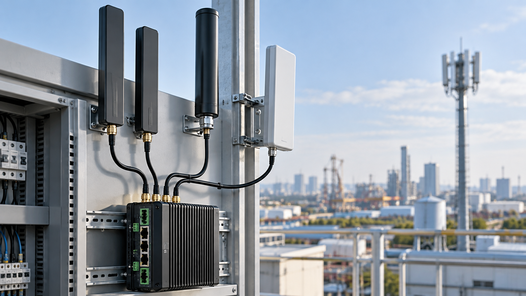
For example, Nova Antenna’s 600–6000 MHz 5G 4×4 MIMO cabinet antenna uses four independent RF feeds and is intended for multi-port cellular equipment. It is one structural example for equipment that actually requires a compatible 4×4 arrangement; it should not be treated as a universal replacement for every 5G router.
3. Choose Omnidirectional or Directional Coverage for the Site
Omnidirectional antennas
An omnidirectional antenna is often practical when the useful signal may arrive from different horizontal directions, when the router location can change, or when a simple fixed installation must work without precise azimuth alignment. Direct-mount paddle antennas and external fiberglass antennas are common mechanical formats for this type of deployment.
Directional antennas
A directional antenna concentrates coverage toward a defined direction. It can be useful for fixed installations where the desired serving direction is known and the antenna can be aligned appropriately. Directional gain should not be interpreted as a universal range improvement: orientation, band support, cable loss, network conditions, and the surrounding environment remain part of the RF link.
4. Treat Gain as One Parameter, Not the Selection Target
Antenna gain describes how radiation is distributed relative to a reference; it does not create additional transmitter power. Higher gain usually changes the radiation pattern, so the best value depends on the required coverage geometry and installation.
For industrial router selection, review gain together with frequency coverage, radiation pattern, efficiency or other available RF data, polarization, MIMO architecture, and installation position. Avoid choosing an antenna solely because one headline dBi value is larger.
5. Minimize Unnecessary RF Cable Loss
Coaxial cable introduces attenuation between the router and antenna, and loss increases with cable length and depends on cable type and frequency. This is especially important when an antenna is moved outside a metal cabinet, to a rooftop, or to a remote pole.
Keep RF cable runs as short as the mechanical installation reasonably allows. If a longer run is unavoidable, select the cable based on its specified attenuation at the operating frequencies and include connectors, adapters, and other RF accessories in the link budget. A remote antenna location is useful only when the placement benefit is not cancelled by excessive feed-line loss.
6. Verify Connector and Mechanical Integration
“SMA” by itself is not a complete interface definition. Confirm connector family and gender on both the router and antenna, and check whether adapters are actually necessary. For cabinet or panel installations, also confirm whether the design requires a direct connector, bulkhead feed-through, integrated cable, or another mounting arrangement.
Mechanical integration should be reviewed at the same time. A folding paddle antenna may suit a router with accessible external ports, while an antenna mounted outside a metal cabinet may require cable routing and a feed-through. Pole- or wall-mounted antennas require appropriate mounting hardware and an installation position that preserves the intended radiation environment.
7. Account for the Installation Environment
Industrial equipment is often installed near metal enclosures, control cabinets, machinery, power electronics, cable bundles, and other RF systems. These surroundings can affect antenna performance and can make a specification measured under controlled conditions different from performance in the final device.
For a related engineering discussion, see multi-band WiFi, LTE and 5G antenna integration.
Avoid placing an antenna inside a closed metal enclosure unless the system was specifically designed and validated for that arrangement. Maintain practical separation from large conductive obstructions and strong interference sources where possible. For outdoor installations, verify the environmental suitability of the complete antenna assembly, connectors, cable entry, and mounting method rather than assuming that every external antenna is weather-rated.
8. Select the Antenna Structure for the Deployment
| Deployment | Typical Antenna Direction | Key Checks |
|---|---|---|
| Router with exposed RF ports | Direct-mount paddle or rod antenna | Band coverage, connector, clearance, orientation, MIMO port count |
| Router inside a metal cabinet | Externally mounted antenna with cable or cabinet-mount structure | Cable loss, feed-through, mounting, separation from metal |
| Fixed outdoor site | Outdoor omni or directional antenna | Required bands, coverage direction, mounting, cable run, environmental suitability |
| Multi-port cellular gateway | Multi-element MIMO antenna or engineered separate-antenna arrangement | Port mapping, MIMO order, polarization/element arrangement, cable identification |
A Practical 5G Industrial Router Antenna Selection Process
- List the required cellular bands. Use the router/modem and target-network documentation.
- Identify every cellular RF port. Record the required MIMO configuration and distinguish cellular ports from WiFi or GNSS ports.
- Define the installation location. Decide whether the antenna will be direct-mounted, outside a cabinet, on a wall/pole, or remotely positioned.
- Choose the required radiation pattern. Use the actual site geometry to decide whether omnidirectional or directional coverage is appropriate.
- Check connector and cable details. Confirm interface gender, cable type, cable length, and any unavoidable adapters.
- Review verified RF specifications. Compare frequency coverage, gain, radiation characteristics, and other available data across the required bands.
- Validate the complete installation. Final performance should be evaluated with the real router, cables, enclosure, mounting arrangement, and target network.
Common Selection Mistakes
- Buying by the “5G” label alone: the actual frequency range still needs to match the deployment.
- Choosing the highest gain number: gain must suit the required radiation pattern and site geometry.
- Ignoring MIMO ports: a multi-port router needs an antenna architecture that supports the intended RF paths.
- Using excessive cable length: a better antenna position can be undermined by feed-line attenuation.
- Assuming connector compatibility: connector family and gender must be checked at both ends.
- Mounting behind metal: cabinets and nearby conductive structures can materially change the RF environment.
- Assuming outdoor suitability: environmental ratings and installation protection should be verified from actual product documentation.
Relevant Nova Antenna Options
Nova Antenna offers cellular antenna structures that can be evaluated for industrial routers and gateways when their verified specifications match the project. One current example is the 600–6000 MHz 5G folding paddle antenna with SMA connector, a direct-mount wideband format intended for cellular routers, gateways, IoT terminals, and industrial wireless equipment.
For equipment designed around multiple cellular paths, the 600–6000 MHz 5G 4×4 MIMO cabinet antenna is another current structural option, with four independent cables and SMA male connectors. Product selection should still begin with the router’s band, port, connector, mounting, and environmental requirements.
Key Information to Send When Requesting an Antenna
For a faster technical review, prepare the router model or modem information, required frequency bands, number of cellular antenna ports, connector interface, target cable length, installation method, available mounting space, and operating environment. If the project requires a specific cable, connector, mounting structure, or antenna form factor, include those constraints before the antenna configuration is finalized.
Explore Nova Antenna’s cellular antenna options or contact Nova Antenna with the router RF requirements to discuss a configuration for an industrial 4G/5G project.