How to Choose a LoRa Antenna for Industrial IoT Devices

A LoRa antenna for industrial IoT should be selected from the radio and deployment requirements outward: confirm the actual operating band, decide whether the antenna serves an embedded node or a gateway, then evaluate antenna structure, connector, cable, enclosure, mounting position, and the required coverage pattern. Choosing only by a “long-range” label or the highest gain value can produce a poor result if the antenna is mismatched to the radio or installed in an unfavorable RF environment.
For industrial sensors, remote monitoring terminals, gateways, meters, and control equipment, the antenna is part of the complete RF system. The practical goal is not to maximize one specification but to preserve usable RF performance after the antenna is integrated into the real device and installation.
Start With the Actual LoRa Operating Band
LoRa products can operate in different sub-GHz frequency ranges depending on the radio design and deployment region. The first antenna-selection step is therefore to identify the exact frequencies the device will transmit and receive on. Do not assume that every antenna described as “LoRa” covers every LoRa deployment.
An antenna intended for 868 MHz operation and one intended for 915 MHz operation may have similar physical forms, but frequency compatibility still needs to be verified from the antenna specification. If one device platform is intended for multiple markets, confirm that the selected antenna has documented coverage for all required bands rather than relying on the product name alone.
| Requirement | What to Confirm | Selection Impact |
|---|---|---|
| Operating frequency | Actual radio channels or required frequency range | Defines the electrical band the antenna must support. |
| Device role | Sensor/node, terminal, or gateway | Influences antenna size, mounting and coverage requirements. |
| RF interface | SMA, IPEX or another verified connector/interface | Determines direct connection or cable requirements. |
| Installation | Internal, direct-mount, cabinet, wall/pole or remote | Changes the suitable antenna structure and cable path. |
| Environment | Indoor, metal enclosure, factory, outdoor or mobile equipment | Affects placement, mechanical design and validation needs. |
Choose the Antenna Around the Device Role
Embedded sensor nodes and compact terminals
Space-constrained IoT nodes often need an internal antenna such as an FPC or another compact embedded structure. This can reduce the external mechanical footprint, but the antenna then operates close to the PCB, battery, enclosure, wiring and other components. Its final performance depends on the complete device layout, not just the standalone antenna specification.
Nova Antenna’s current 868/915 MHz internal FPC antenna is one example of this form factor. The published product information specifies a 43 × 20 × 0.2 mm FPC element, RG1.13 cable, and IPEX or solder connection options. It can be considered when those verified electrical and mechanical characteristics match an embedded LoRa or IoT design.
Industrial gateways and external terminals
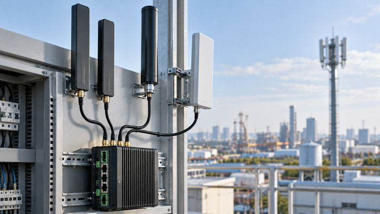
A gateway or larger industrial terminal often has more freedom to use an external antenna. Direct-mount rubber-rod antennas can simplify equipment integration when the RF connector is exposed, while remotely mounted antennas can move the radiating element away from a cabinet or obstruction. Remote mounting, however, introduces feed-line loss and additional connector and weather-protection considerations.
For example, Nova Antenna currently lists an 868/915 MHz rubber-rod antenna with an SMA male connector, omnidirectional radiation and an adjustable swivel structure. This is a different integration approach from an internal FPC antenna; the appropriate choice depends on the device interface and installation rather than on one form factor being universally better.
Do Not Choose Gain Without Considering the Radiation Pattern
Antenna gain describes how radiation is distributed in space relative to a reference. A higher gain value does not automatically mean better communication in every direction or every installation. For a sensor network with devices distributed around a gateway, a practical omnidirectional pattern may be more useful than concentrating energy toward a narrow direction.
Directional antennas can be useful when the coverage area is intentionally concentrated in a known direction, but they require appropriate alignment and site geometry. For either approach, evaluate gain together with radiation pattern, antenna orientation, installation height, surrounding obstructions and the locations of the communicating devices.
Check Connector Type Before Ordering
Connector compatibility is a simple issue that can stop an otherwise correct antenna from being usable. Confirm the connector family and mating interface on the radio or enclosure before selecting the antenna. An embedded module may use a miniature IPEX-style connection, while an industrial gateway may expose an SMA or another external RF interface.
Avoid adding adapters unless they are genuinely required. Every additional RF interface adds mechanical complexity and contributes some insertion loss. For production equipment, connector selection should also consider assembly access, strain on the PCB or cable, vibration and service requirements.
Include Cable Loss in the RF Decision
Coaxial cable introduces attenuation between the radio and antenna. The amount depends on cable type, length and frequency. This matters when an antenna is moved outside a metal control cabinet or installed remotely on a wall, mast or rooftop.
Keep the cable only as long as the installation requires. When a long cable run is unavoidable, use the cable manufacturer’s attenuation data at the relevant operating frequency and include connectors or other inline RF components in the link budget. A remote antenna position is beneficial only when the placement improvement is not cancelled by excessive feed-line loss.
Account for the Enclosure and Nearby Materials
Industrial IoT devices are often installed near metal cabinets, batteries, displays, wiring, motors and other electronics. These materials can change the antenna’s RF environment. An internal antenna that performs well in open space can behave differently after it is bonded to an enclosure wall or placed close to a ground plane or battery.
For a broader device-level selection framework, see matching antennas to different IoT application needs.
For embedded designs, reserve antenna space early and avoid treating placement as a final mechanical detail. For external antennas, avoid unnecessary shielding by metal structures and check that the installed orientation matches the intended radiation behavior. The final antenna should be validated in the assembled device rather than judged only from a loose bench setup.
Select Internal or External Antenna Architecture
| Architecture | Typical Strength | Key Engineering Check |
|---|---|---|
| Internal FPC antenna | Compact and easy to integrate inside an enclosure | Placement, nearby materials, cable routing and connector access |
| Direct-mount rod antenna | Simple external connection with no long feed cable | Connector match, mechanical clearance and orientation |
| Remote external antenna | Can move the antenna away from a cabinet or obstruction | Cable attenuation, mounting location and environmental protection |
| Directional external antenna | Concentrates coverage toward a defined area | Alignment, coverage geometry and site stability |
Consider the Installation Environment
An antenna used indoors in a plastic sensor housing faces different mechanical requirements from an antenna mounted outside a factory building. Do not assume that an antenna is suitable for outdoor use simply because it is external. Verify the documented environmental characteristics of the exact product and protect connectors, cable entries and mounting points as required by the final equipment design.
Industrial sites can also contain large conductive structures and sources of electrical noise. Antenna position should therefore be evaluated as part of the site installation. Where practical, test representative locations before fixing the final mounting position for a gateway or remote terminal.
A Practical LoRa Antenna Selection Process
- Record the radio frequency requirements. Use the device and radio-module documentation to identify the actual operating band.
- Define the device role. Separate the constraints of a compact sensor node from those of an industrial gateway or external terminal.
- Choose internal or external integration. Base this on enclosure material, available space, RF connector location and installation environment.
- Confirm the connector. Verify connector family and mating interface before ordering.
- Review cable requirements. Minimize unnecessary cable length and account for attenuation when remote mounting is required.
- Evaluate gain and radiation pattern together. Match the coverage geometry instead of selecting the largest dBi number.
- Check mechanical and environmental constraints. Confirm mounting, clearance and any required environmental protection from actual product documentation.
- Validate the assembled system. Test the antenna with the production-intent enclosure, cable path, radio and representative installation conditions.
Common LoRa Antenna Selection Mistakes
- Buying by the “LoRa” label alone: the documented frequency range still has to match the radio.
- Assuming 868 MHz and 915 MHz are automatically interchangeable: verify antenna coverage for the actual frequencies used.
- Choosing only by gain: radiation pattern and installation geometry are equally important.
- Ignoring the enclosure: batteries, metal, PCB ground and nearby structures can change antenna behavior.
- Using unnecessary adapters or long cables: they add complexity and RF loss.
- Leaving antenna placement until the end of the mechanical design: embedded antennas need intentional space and integration.
- Assuming an external antenna is automatically outdoor-rated: environmental suitability must be verified for the exact product and installation.
Relevant Nova Antenna Options
Nova Antenna’s LoRa antenna category can be used as a starting point for current sub-GHz antenna formats. Product selection should still be based on verified frequency, connector, mechanical and installation requirements.
Review the current LoRa Antennas category for available formats.
For compact embedded equipment, the current 868/915 MHz internal FPC antenna provides an internal adhesive-backed structure with RG1.13 cable and IPEX or solder options. For equipment with an exposed external RF port, the current 868/915 MHz rubber-rod antenna provides an SMA male interface and adjustable omnidirectional form factor. These examples illustrate different integration approaches rather than universal recommendations.
Information to Prepare for a LoRa Antenna Request
Before requesting an antenna configuration, prepare the operating frequency or regional radio version, radio module or device information, connector interface, available antenna space, enclosure material, target cable length, mounting method and operating environment. For a gateway, also describe where the antenna will be installed relative to the coverage area and whether remote mounting is required.
If your industrial IoT project requires a specific frequency, connector, cable length or antenna structure, review the current LoRa antenna options or contact Nova Antenna with the RF and mechanical requirements for technical evaluation.