UAV Antenna Selection and Installation Checklist
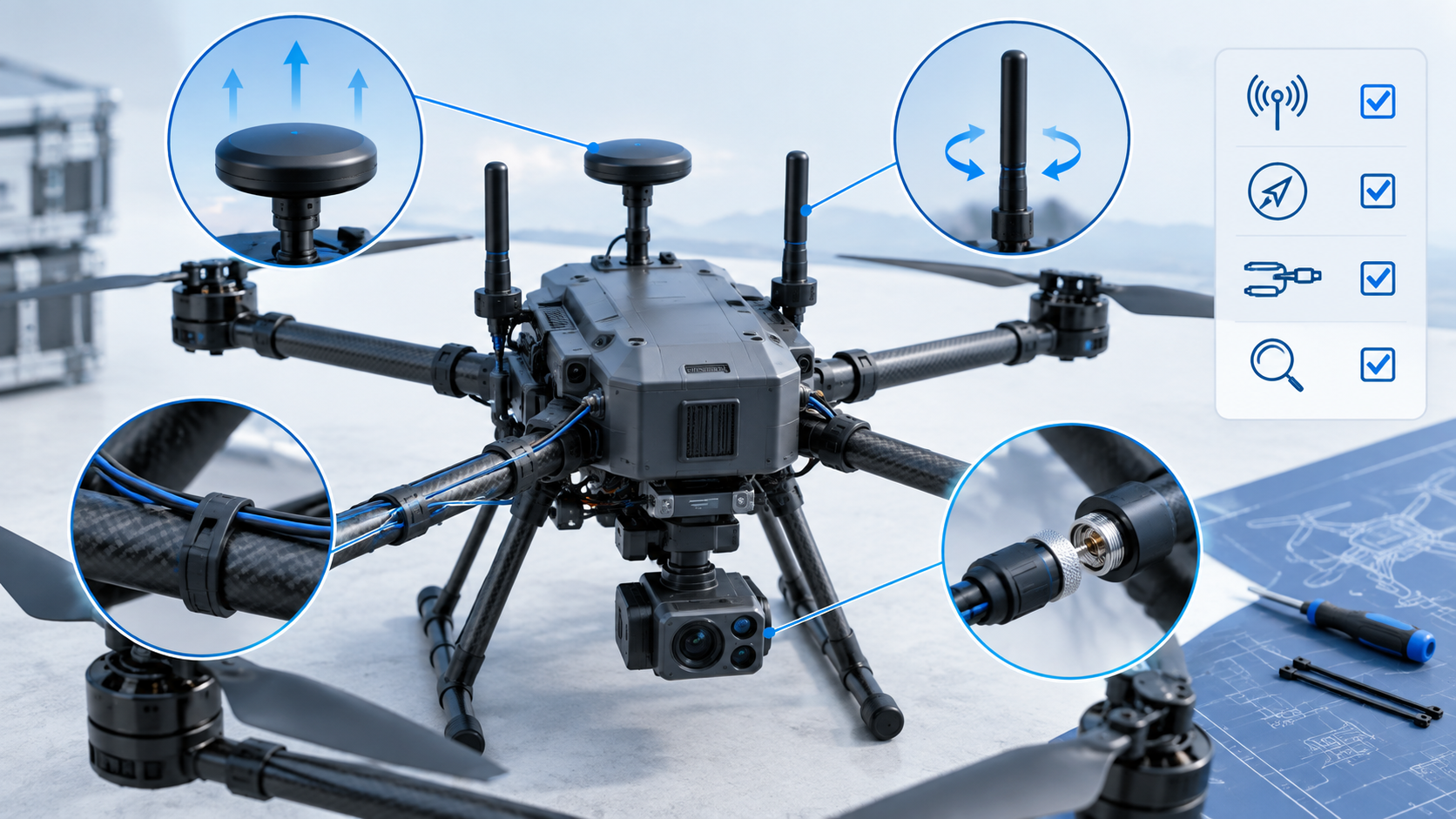
Choosing the right UAV antenna requires more than matching a frequency band. The antenna must also fit the aircraft’s RF architecture, installation space, cable and connector configuration, operating environment, and expected flight conditions.
For UAV manufacturers and system integrators, antenna selection and installation should therefore be treated as one engineering process. A suitable antenna on a specification sheet may perform differently after integration because of its position, orientation, nearby materials, cable routing, or other onboard electronics.
UAV Antenna Checklist at a Glance
Before approving an antenna configuration, check:
- Wireless function: command and control, telemetry, video, positioning, or another RF link
- Required operating frequency or band
- Radiation characteristics and polarization
- Gain requirements within the complete link design
- Antenna size, weight, and mounting constraints
- Connector and mating-interface compatibility
- RF cable type, length, routing, and strain relief
- Nearby airframe materials and electronic systems
- Relationship with other onboard antennas
- Environmental and mechanical requirements
- Final installed configuration
- Post-installation RF and mechanical verification
Exact requirements should always come from the radio system, aircraft design, applicable regulations, and verified antenna data.
1. Define the UAV RF Requirements First
Before comparing antennas, identify exactly what each antenna must do.
Identify Each Wireless Function
A UAV may use separate RF links for command and control, telemetry, video transmission, positioning, or other wireless functions. Each can have different frequency, radiation, installation, and system-level requirements.
For multi-radio UAVs, create an antenna map showing which antenna belongs to each transmitter, receiver, or transceiver. Do not assume physically similar antennas are interchangeable.
Confirm Frequency and Bandwidth
The antenna’s verified operating range must correspond to the radio system.
Check the complete required frequency range rather than only a nominal center frequency. If the radio uses multiple channels or a wider band, confirm that the antenna documentation supports that range.
Frequency compatibility is essential, but frequency alone does not determine whether an antenna is suitable for a UAV.
Define Mechanical and Interface Constraints
Document the available installation space, acceptable antenna dimensions and weight, mounting method, nearby airframe materials, expected orientation, connector interface, cable type, required cable length, and routing path.
Separate mandatory requirements from preferences. For example, the radio band and mating interface may be fixed, while several antenna form factors or mounting positions may still be possible.
2. UAV Antenna Selection Checklist
Once the system requirements are defined, evaluate each candidate as part of the complete aircraft installation.
To explore available antenna formats, review Nova Antenna’s Drone & UAV Antennas category, then compare each candidate’s verified specifications with your RF and mechanical requirements.
Radiation Pattern, Polarization, and Gain
Consider how the aircraft communicates during actual operation.
Radiation requirements depend on aircraft movement, ground-station geometry, antenna orientation, link type, and the desired coverage pattern. Polarization should also be considered in relation to the antenna at the other end of the RF link and the UAV’s expected pitch, roll, and yaw.
Higher gain is not automatically better. Gain changes how RF energy is distributed spatially, so it must be considered together with radiation pattern, aircraft orientation, radio characteristics, regulatory constraints, and the overall link design.
Do not use antenna gain alone to predict communication distance.
Size, Weight, and Mounting
Confirm that the antenna fits the installation envelope, can be mounted securely, maintains the required orientation, and does not interfere with payloads or moving components.
Neither the smallest nor the largest antenna is automatically the best choice. RF and mechanical requirements must be evaluated together.
Connector and RF Cable
Verify the exact mating interfaces used by the radio, antenna, cable assembly, and any intermediate RF components.
Connectors that look similar are not necessarily interchangeable. RF cable also forms part of the transmission path: cable loss, excessive bending, damaged connectors, mechanical stress, or poor assembly can affect the installed system.
Plan the cable configuration before finalizing the antenna location.
Environmental Requirements
Define requirements from the UAV’s real operating conditions. Depending on the application, this may include vibration, temperature, moisture exposure, cable movement, connector retention, or repeated assembly.
Do not assume an environmental rating or certification unless it is documented for the selected component or assembly.
For related background, see environmental factors affecting UAV onboard antenna communication. Use the discussion alongside the selected component’s verified documentation and your aircraft-level validation plan.
3. UAV Antenna Installation Checklist
A technically suitable antenna can still produce poor system results if installed in an unfavorable RF environment.
Review Position and Orientation
Evaluate the antenna position relative to the airframe and its intended radiation behavior.
Metal, carbon-fiber structures, batteries, electronics, wiring, payloads, and other nearby components may alter the local RF environment. The effect depends on frequency, antenna design, geometry, material, and installation.
Avoid universal spacing rules unless they are supported by the specific design or test data.
Install the antenna in the orientation required by the approved RF design. If the UAV operates over a wide range of attitudes, evaluate representative orientations rather than only a stationary aircraft.
Consider Other Onboard RF Systems
Multi-radio UAVs should be evaluated as complete RF systems.
Nearby antennas can interact through coupling, simultaneous transmission, receiver desensitization, or changes in the surrounding RF environment. Document all onboard transmitters and receivers and evaluate their relationships during integration.
Do not assume the layout is acceptable simply because each antenna works correctly when tested alone.
Route and Secure RF Cables
Avoid sharp bends, persistent connector loads, unnecessary cable length, and routing that exposes the cable to mechanical damage.
Provide suitable cable support and strain relief. Where relevant, consider RF cable routing in relation to power wiring, motors, electronic speed controllers, digital electronics, and other potential noise sources.
Also verify clearance from propellers, control surfaces, landing mechanisms, payload movement, removable covers, and other moving components.
4. Verify the Final UAV Configuration
Antenna selection and installation checks do not replace system validation.
Before flight testing, inspect the antenna, cable, connectors, and mounting for visible damage, loose connections, deformation, unsupported cable weight, unexpected bends, or movement.
Confirm that the final aircraft uses:
- The correct antenna for each RF subsystem
- The approved mounting location and orientation
- The correct connector and cable configuration
- Secure mechanical mounting
- The intended relationship between onboard antennas
Perform this review with the aircraft in a configuration representative of actual operation, including relevant batteries, covers, payloads, wiring, and RF systems.
Record the antenna identification, mounting position, orientation, cable assembly, connector configuration, aircraft revision, payload configuration, and relevant test conditions. This helps distinguish actual antenna performance from uncontrolled installation changes.
If a payload, enclosure, battery position, cable, radio, structure, or another antenna changes later, determine whether renewed RF verification is necessary.
5. Common UAV Antenna Integration Mistakes
Several problems can be reduced by treating antenna integration as a system-level task:
- Selecting an antenna before defining the wireless link requirements
- Choosing primarily by frequency, gain, or physical size
- Installing the antenna wherever space happens to be available
- Changing the cable or connector configuration without re-evaluation
- Ignoring interactions between multiple onboard RF systems
- Testing only an incomplete aircraft configuration
- Skipping post-installation verification
Component specifications describe performance under defined conditions. They do not by themselves prove the performance of the final UAV installation.
6. When a Custom UAV Antenna May Be Required
A custom configuration may be worth evaluating when a standard antenna satisfies much of the RF requirement but cannot meet important integration constraints.
Typical reasons can include limited installation space, unusual mounting geometry, connector requirements, cable configuration, or application-specific RF requirements.
Before discussing customization, prepare as much of the following information as possible:
- Wireless function
- Required frequency or band
- Radio and RF interface information
- Available installation space
- Proposed antenna mounting location
- Materials surrounding the antenna
- Connector and cable requirements
- Weight and mechanical constraints
- Environmental requirements
- Other onboard RF systems
- Project-specific validation requirements
Customization should not be treated as a cosmetic change. Changing an antenna, cable, connector, or feed configuration may require renewed engineering evaluation and verification.
Final Takeaway
Successful UAV antenna integration begins with clearly defined RF and mechanical requirements.
Start by identifying each wireless function and its required frequency range. Then evaluate radiation characteristics, polarization, gain, size, weight, mounting, connector and cable requirements as parts of the complete RF system. During installation, consider the airframe, nearby electronics, other antennas, cable routing, mechanical clearance, and the UAV’s representative final configuration.
Most importantly, do not treat antenna selection data as proof of final aircraft performance. Document the installed configuration and verify the completed UAV system under project-appropriate conditions.
A well-defined requirement package makes it easier to determine whether an existing antenna configuration is suitable or whether a customized solution needs to be evaluated.